Page 14 - Steel Tech India eMagazine Volume April 2022
P. 14

VOL. 16 • NO. 3 • April 2022

                 Some  typical  ladle/  billet  sample  analysis  of  some   amount. Since, conventional induction furnace lining is
                 induction melted steel using 65-75 % cDRI are given in   silica based, building a basic slag inside the furnace
                 table 1 under for reference.                       which is a necessary condition to reduce phosphorus is
                                                                    not possible. to overcome this problem and to build up
                 Table 1: Billet Sample Analysis
                                                                    an basic slag.  efforts were taken  to use neutral lining
                  Heat  %C %Mn      %S     %P    %Si   %Cr   %Al    in the furnace instead of silica and thus  to allow build
                   No                                               up of basic slag with higher basicity and using iron ore/
                    1   0.13  0.47  0.038  0.092  0.16  0.01  0.007  mill scale to increase FeO in the slag and even some
                    2   0.19  0.50  0.038  0.090  0.14 0.009 0.008  customised de phosphorising compound.  But all such
                                                                    efforts did not fare well and the purpose was not fulfilled
                    3   0.18  0.46  0.037  0.086  0.17  0.01  0.009  because it increased the tap to tap time of the process

                    4   0.17  0.53  0.040  0.095  0.19  0.01  0.006  reducing the productivity andsequence castinglength
                    5   0.18  0.56  0.046  0.090  0.15  0.02  0.009  and hence process efficiency was badly impacted. the
                                                                    cost of neutral lining was also high.
                    6   0.24  0.60  0.040  0.092  0.20  0.01  0.008  Finally it was thought of  for  exploring  ladle furnace

                 From the above examples, it can be seen that the P   treatment instead of in situ  treatment in the IF itself
                 levels are generally very high exceeding 0.08 %and   for reducing the  P content  and after initial   dilemma,
                 is not a good fit for the final application worthiness for   especially on sustenance of the process and cost of
                 rebar and structural.                              treatment, few progressive IF plants ventured into  the
                                                                    use of secondary refining  with  encouraging results in
                 Some attempts in the past were made to explore how   reduction of P and to some extent S as well.. A snapshot
                 this P level could be reduced while using high cDRI   of the process adopted and the process flow sheet is
                  IF crucible Aim tap    c-.<0.10    tap to lRF      lRF             ADDN- De Oxydiser/     caster
                  DRI 75 %    chemistry  Mn < 0.05   With addition of   treatmentwith   Ferro Alloys/Slag
                  Pig-10 %               Si- <0.01   lime/Mill Scale/   gas purging -   cover to Adjust Final
                  Scrap 15%                                          Slag Off        chemistry /temp
                                                     Iron Ore

                                                                    shown as under:-

                                                                    Study  on  the  Process  Parameters/  Specific
                                                                    Consumptions:

                                                                    As we are aware that phosphorus removal during steel
                                                                    making process happens under oxidising condition with
                                                                    a highly basic slag which absorbs the phosphorus in
                                                                    form of phosphorus  pent oxide  as per the following
                                                                    reactions
                                                                    2P + 5O = P O
                                                                               2  5
                                                                    P O  + 4CaO = 4CaO P O  5
                                                                      2
                                                                        5
                                                                                          2
                                                                    these reactions are, part one is a volume zone and the
                                                                    part two is a slag metal reaction. Since one molecule
                                                                    of P O  combines with 4 molecules of  caO form the
                                                                        2
                                                                          5
                                                                    slag, the lime content and the basicity of slag needs
                                                                    to be high. Again P O  has a rather lower dissociation
                                                                                        5
                                                                                      2
                                                                    temperature and hence the dephosphorization process
                                                                    to be controlled at optimum temperature to avoid any
                                                                    P reversion in the steel.  therefore the ladle furnace
                                                                    operation for this very purpose needs critical controls.
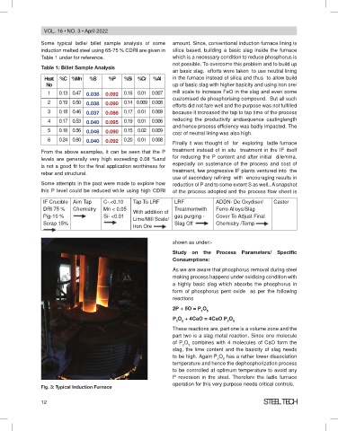
                 Fig. 3: Typical Induction Furnace

                 12                                                                                     Steel tech
   9   10   11   12   13   14   15   16   17   18   19